2. ファイアウォール・ロードバランサー構成例(ツーアーム)※クライアントのIPアドレス変換なし
2.1. 前提条件
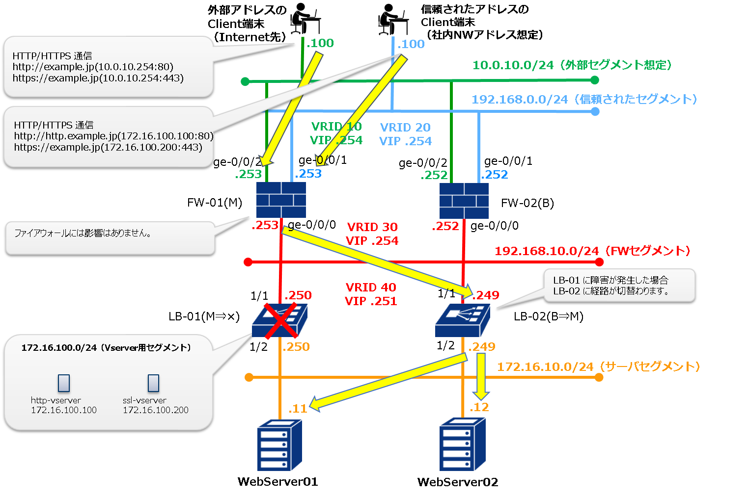
WEBサーバーを外部に公開するため、以下の方針でファイアウォール(以下FW)とロードバランサー(以下LB)を設定します。
ファイアウォール
VRRPを使用して2台の冗長構成とします。すべてのネットワークセグメントでVRRPを設定します。
FWルールは外部セグメントからの通信は基本すべて拒否し、特定のHTTP通信・HTTPS通信のみ許可します。信頼されたセグメントからの通信はすべて許可とします。
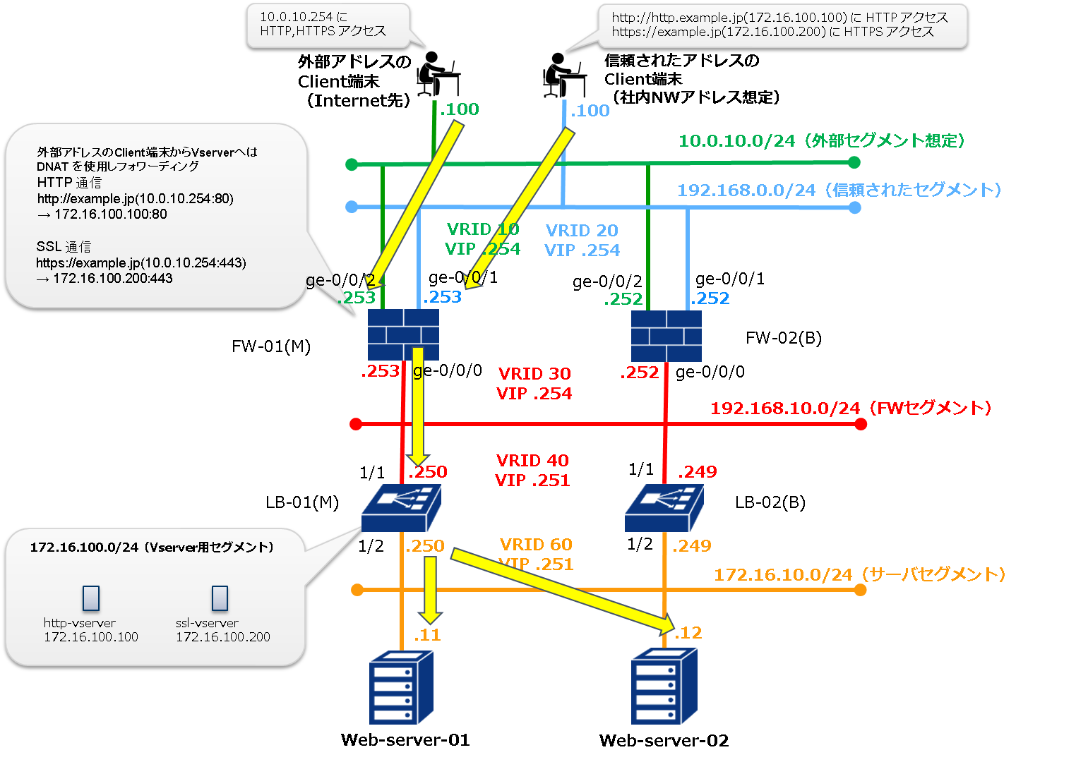
外部セグメントからはLBのバーチャルサーバーのIPアドレスではなく、FWのグローバルIPアドレスにアクセスさせ、NAT変換で宛先をバーチャルサーバーのIPアドレスに変換します。
VRRPのpreemptはデフォルトのまま有効(True)としてしてください。preemptが無効になっていると全インターフェイスでステータスが一致せず、通信断が継続することがあります。
ロードバランサー
VRRPを使用して2台冗長構成とします。FWセグメントでVRRPを構築します。
HTTP通信・HTTPS通信用のバーチャルサーバーを立て、2台のWEBサーバーにラウンドロビンで通信を分散します。HTTPSはSSLオフロードを行います。
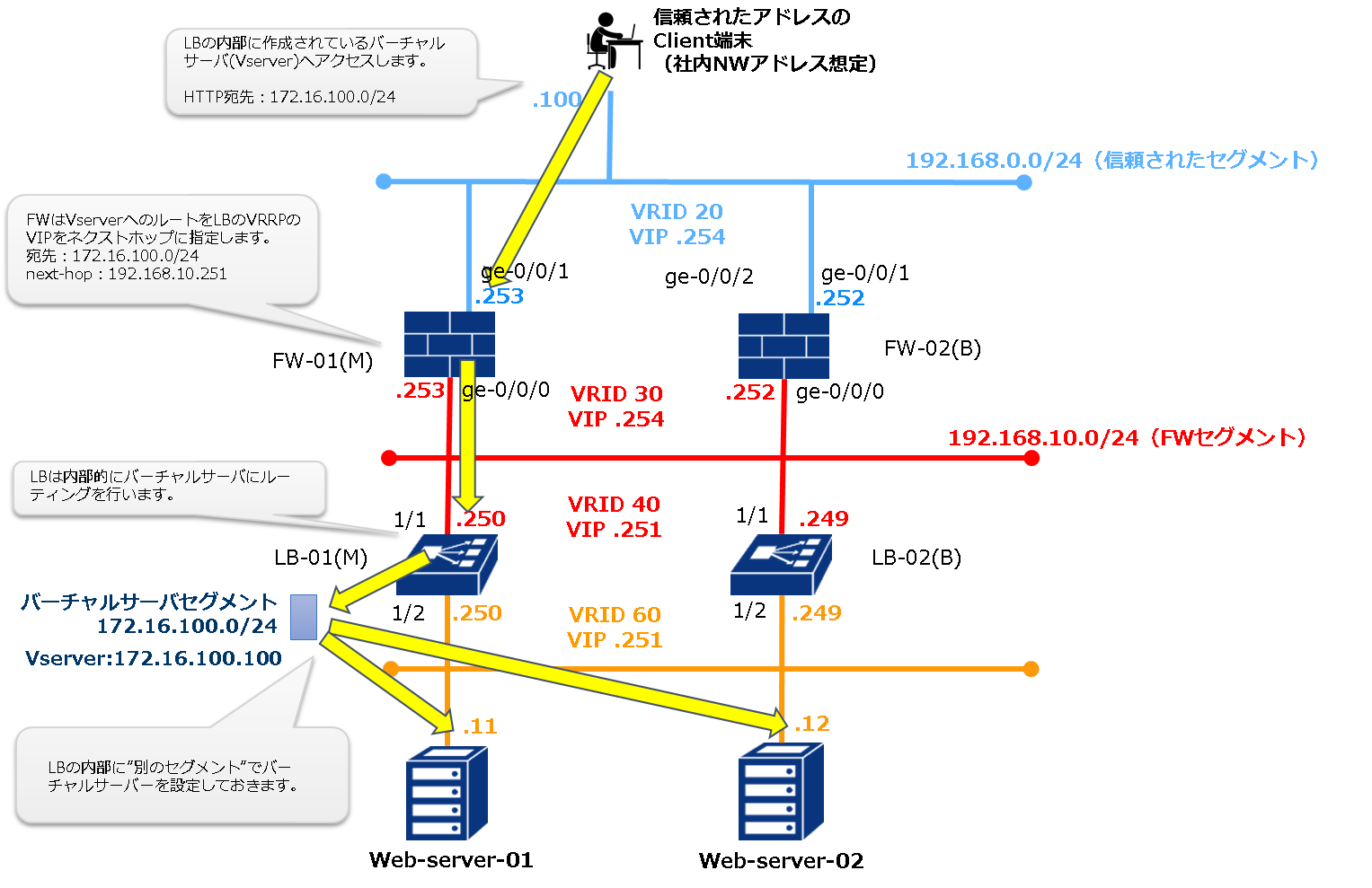
SDPFのLB(NetScalerVPX)では、1つのインターフェイスに対して登録可能なVRRP設定(仮想IPアドレスとVRRPグループIDのペア)は1つであり、複数のVRRPグループの登録はできません。代替方法としてVRRP用に登録したVirtual IPアドレス(以下VIP)とは別のセグメントに仮想IPアドレスを登録し、それを振り分け対象IPアドレスに設定することで複数VIPを冗長化させることができます。本構成はこの方法で冗長構成としています。
VRRPのpreemptはデフォルトのまま有効(True)としてください。preemptが無効になっている場合、全インターフェイスでステータスが一致せず、通信断が継続することがあります。
WebサーバーのデフォルトゲートウェイはLBのInterfce 1/2側のVIPとしてください。SDPFでは通信が往復で同じ経路を通る構成としてください。
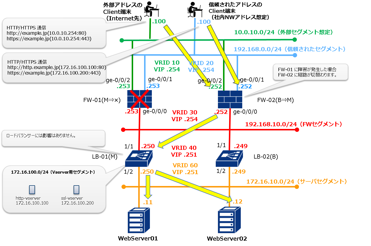
設定概念のイメージ
2.2. システム構成図
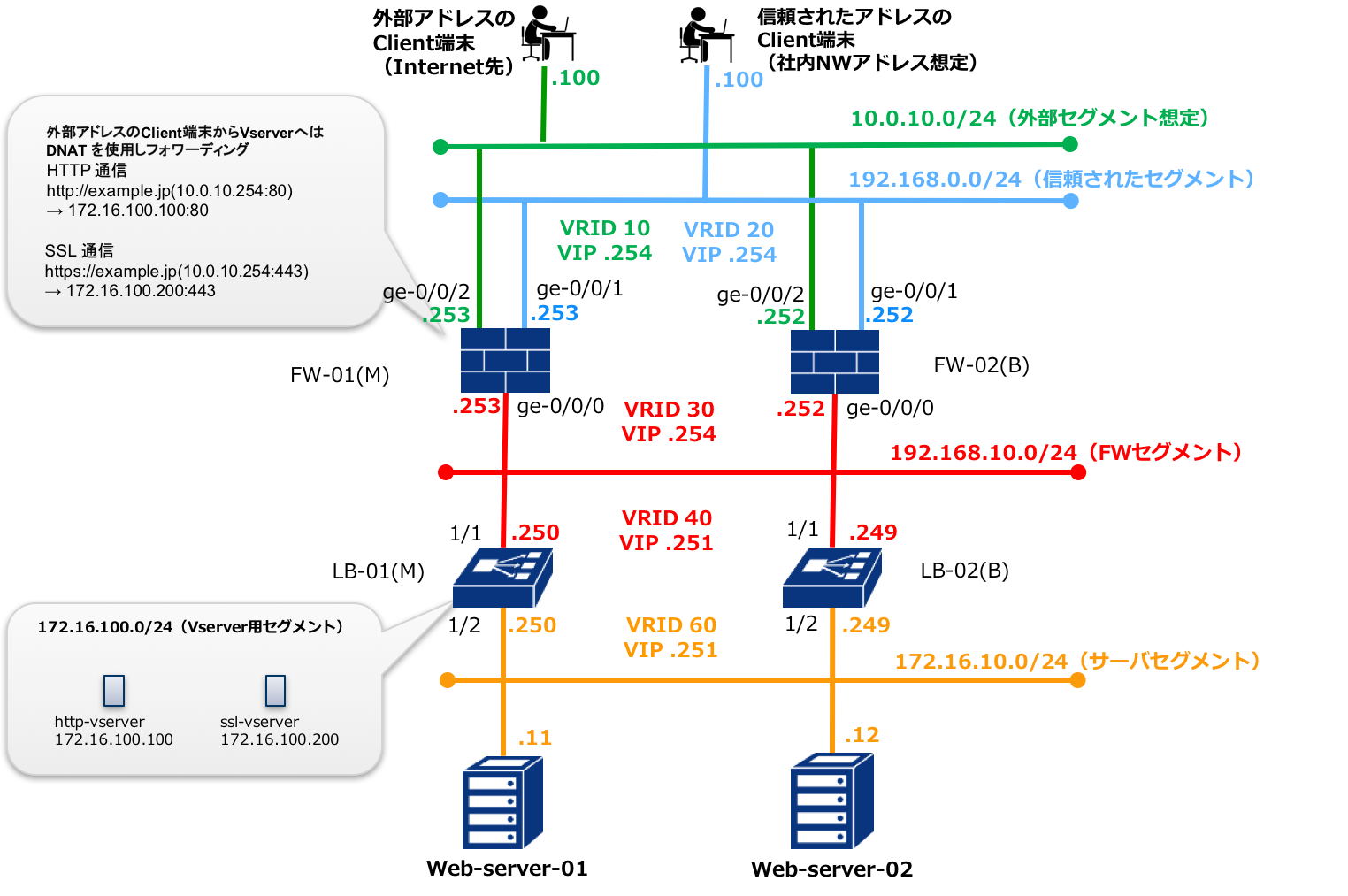
注釈
その他のコンポーネントの利用OSやVersionは以下のとおりです。
WebServer01,02
OS CentOS7.3.1611
Webサーバー Apache 2.4.6
Client端末
Windows Server 2012R2
2.3. ファイアウォール設定の内容
ファイアウォールインターフェイス設定
注釈
vSRXへのインターフェイスのIPアドレス設定前に、Smart Data Platformポータル(以下SDPFポータル)画面で利用インターフェイスとIPアドレス設定をお願いします。
インターフェイス(ge-0/0/0)は「FWセグメント」に接続するインターフェイスとして設定します。
インターフェイス(ge-0/0/1)は「信頼されたセグメント」に接続するインターフェイスとして設定します。
インターフェイス(ge-0/0/2)は「外部セグメント」に接続するインターフェイスとして設定します。
FW-01
# set interfaces ge-0/0/0 unit 0 family inet address 192.168.10.253/24
# set interfaces ge-0/0/1 unit 0 family inet address 192.168.0.253/24
# set interfaces ge-0/0/2 unit 0 family inet address 10.0.10.253/24
FW-02
# set interfaces ge-0/0/0 unit 0 family inet address 192.168.10.252/24
# set interfaces ge-0/0/1 unit 0 family inet address 192.168.0.252/24
# set interfaces ge-0/0/2 unit 0 family inet address 10.0.10.252/24
ファイアウォールインターフェイスをゾーンに割り当て
注釈
FWのインターフェイスではVRRPを利用していますので、VRRPの管理パケットを着信するために必ずVRRPを許可する設定にします。その他のルールについては、お使いの環境に合わせて必要なルールを設定してください。
FW-01/FW-02
# set security zones security-zone trust interfaces ge-0/0/0.0
# set security zones security-zone trust interfaces ge-0/0/1.0
# set security zones security-zone trust host-inbound-traffic system-services all
# set security zones security-zone trust host-inbound-traffic  protocols all
# set security zones security-zone untrust interfaces ge-0/0/2.0
# set security zones security-zone untrust host-inbound-traffic system-services ping
# set security zones security-zone untrust host-inbound-traffic  protocols vrrp
VRRP設定
FW-01
インターフェイス(ge-0/0/0)のVRRP設定
# set interfaces ge-0/0/0 unit 0 family inet address 192.168.10.253/24 vrrp-group 30 virtual-address 192.168.10.254
# set interfaces ge-0/0/0 unit 0 family inet address 192.168.10.253/24 vrrp-group 30 priority 110
# set interfaces ge-0/0/0 unit 0 family inet address 192.168.10.253/24 vrrp-group 30 preempt
# set interfaces ge-0/0/0 unit 0 family inet address 192.168.10.253/24 vrrp-group 30 accept-data
# set interfaces ge-0/0/0 unit 0 family inet address 192.168.10.253/24 vrrp-group 30 advertise-interval 5
インターフェイス(ge-0/0/1)のVRRP設定
# set interfaces ge-0/0/1 unit 0 family inet address 192.168.0.253/24 vrrp-group 20 virtual-address 192.168.0.254
# set interfaces ge-0/0/1 unit 0 family inet address 192.168.0.253/24 vrrp-group 20 priority 110
# set interfaces ge-0/0/1 unit 0 family inet address 192.168.0.253/24 vrrp-group 20 preempt
# set interfaces ge-0/0/1 unit 0 family inet address 192.168.0.253/24 vrrp-group 20 accept-data
# set interfaces ge-0/0/1 unit 0 family inet address 192.168.0.253/24 vrrp-group 20 advertise-interval 5
インターフェイス(ge-0/0/2)のVRRP設定
# set interfaces ge-0/0/2 unit 0 family inet address 10.0.10.253/24 vrrp-group 10 virtual-address 10.0.10.254
# set interfaces ge-0/0/2 unit 0 family inet address 10.0.10.253/24 vrrp-group 10 priority 110
# set interfaces ge-0/0/2 unit 0 family inet address 10.0.10.253/24 vrrp-group 10 preempt
# set interfaces ge-0/0/2 unit 0 family inet address 10.0.10.253/24 vrrp-group 10 accept-data
# set interfaces ge-0/0/2 unit 0 family inet address 10.0.10.253/24 vrrp-group 10 advertise-interval 5
FW-02
インターフェイス(ge-0/0/0)のVRRP設定
# set interfaces ge-0/0/0 unit 0 family inet address 192.168.10.252/24 vrrp-group 30 virtual-address 192.168.10.254
# set interfaces ge-0/0/0 unit 0 family inet address 192.168.10.252/24 vrrp-group 30 priority 90
# set interfaces ge-0/0/0 unit 0 family inet address 192.168.10.252/24 vrrp-group 30 preempt
# set interfaces ge-0/0/0 unit 0 family inet address 192.168.10.252/24 vrrp-group 30 accept-data
# set interfaces ge-0/0/0 unit 0 family inet address 192.168.10.252/24 vrrp-group 30 advertise-interval 5
インターフェイス(ge-0/0/1)のVRRP設定
# set interfaces ge-0/0/1 unit 0 family inet address 192.168.0.252/24 vrrp-group 20 virtual-address 192.168.0.254
# set interfaces ge-0/0/1 unit 0 family inet address 192.168.0.252/24 vrrp-group 20 priority 90
# set interfaces ge-0/0/1 unit 0 family inet address 192.168.0.252/24 vrrp-group 20 preempt
# set interfaces ge-0/0/1 unit 0 family inet address 192.168.0.252/24 vrrp-group 20 accept-data
# set interfaces ge-0/0/1 unit 0 family inet address 192.168.0.252/24 vrrp-group 20 advertise-interval 5
インターフェイス(ge-0/0/2)のVRRP設定
# set interfaces ge-0/0/2 unit 0 family inet address 10.0.10.252/24 vrrp-group 10 virtual-address 10.0.10.254
# set interfaces ge-0/0/2 unit 0 family inet address 10.0.10.252/24 vrrp-group 10 priority 90
# set interfaces ge-0/0/2 unit 0 family inet address 10.0.10.252/24 vrrp-group 10 preempt
# set interfaces ge-0/0/2 unit 0 family inet address 10.0.10.252/24 vrrp-group 10 accept-data
# set interfaces ge-0/0/2 unit 0 family inet address 10.0.10.252/24 vrrp-group 10 advertise-interval 5
ファイアウォールフィルタの設定
外部セグメントからの通信についてアクセス制御を行うルールを作成します。
基本はすべて拒否
FW-01とFW-02間のVRRP通信は許可
Webアクセスに利用するIPアドレス(10.0.10.254)へは、HTTP(80),HTTPS(443)通信のみ許可
FW-01
# set firewall filter WEB-ACCESS term 1 from destination-address 10.0.10.254/32
# set firewall filter WEB-ACCESS term 1 from protocol tcp
# set firewall filter WEB-ACCESS term 1 from destination-port http
# set firewall filter WEB-ACCESS term 1 from destination-port https
# set firewall filter WEB-ACCESS term 1 then accept
# set firewall filter WEB-ACCESS term 2 from source-address 10.0.10.252/32
# set firewall filter WEB-ACCESS term 2 from protocol vrrp
# set firewall filter WEB-ACCESS term 2 then accept
# set firewall filter WEB-ACCESS term 3 then discard
FW-02
# set firewall filter WEB-ACCESS term 1 from destination-address 10.0.10.254/32
# set firewall filter WEB-ACCESS term 1 from protocol tcp
# set firewall filter WEB-ACCESS term 1 from destination-port http
# set firewall filter WEB-ACCESS term 1 from destination-port https
# set firewall filter WEB-ACCESS term 1 then accept
# set firewall filter WEB-ACCESS term 2 from source-address 10.0.10.253/32
# set firewall filter WEB-ACCESS term 2 from protocol vrrp
# set firewall filter WEB-ACCESS term 2 then accept
# set firewall filter WEB-ACCESS term 3 then discard
作成したFWルールをインターフェイスに適用します。
FW-01/FW-02
# set interfaces ge-0/0/2 unit 0 family inet filter input WEB-ACCESS
NATの設定
外部セグメントからFWに対するHTTP通信先・HTTPS通信先をLBに設定されているバーチャルサーバーのアドレスへ変更するNATの設定を行います。
FW-01/FW-02
# set security nat destination pool HTTP_NAT address 172.16.100.100/32
# set security nat destination pool HTTPS_NAT address 172.16.100.200/32
# set security nat destination rule-set 1 from zone untrust
# set security nat destination rule-set 1 rule 1 match destination-address 10.0.10.254/32
# set security nat destination rule-set 1 rule 1 match destination-port 80
# set security nat destination rule-set 1 rule 1 match protocol tcp
# set security nat destination rule-set 1 rule 1 then destination-nat pool HTTP_NAT
# set security nat destination rule-set 1 rule 2 match destination-address 10.0.10.254/32
# set security nat destination rule-set 1 rule 2 match destination-port 443
# set security nat destination rule-set 1 rule 2 match protocol tcp
# set security nat destination rule-set 1 rule 2 then destination-nat pool HTTPS_NAT
セキュリティポリシーの設定
アドレスブックの作成(FW-01/FW-02)
LBのバーチャルサーバーのIPアドレスを定義します。
# set security address-book global address WEB_ADDRESS 172.16.100.0/24
アプリケーションセットの作成(FW-01/FW-02)
使用するアプリケーションのポート番号をグループ化します。
# set applications application HTTP protocol tcp
# set applications application HTTP destination-port 80
# set applications application HTTPS protocol tcp
# set applications application HTTPS destination-port 443
# set applications application-set WEB-SERVICE application HTTP
# set applications application-set WEB-SERVICE application HTTPS
ポリシーへの割り当て(FW-01/FW-02)
# set security policies from-zone untrust to-zone trust policy WEB_ACCESS match source-address any
# set security policies from-zone untrust to-zone trust policy WEB_ACCESS match destination-address WEB_ADDRESS
# set security policies from-zone untrust to-zone trust policy WEB_ACCESS match application WEB-SERVICE
# set security policies from-zone untrust to-zone trust policy WEB_ACCESS then permit
# set security policies from-zone untrust to-zone trust policy ALL-DENY match source-address any
# set security policies from-zone untrust to-zone trust policy ALL-DENY match destination-address any
# set security policies from-zone untrust to-zone trust policy ALL-DENY match application any
# set security policies from-zone untrust to-zone trust policy ALL-DENY then deny
注釈
trustゾーンからの通信はデフォルトで許可するポリシー(default-permit)設定がされているのでそのまま利用します。
ルーティングの設定
FWからのバーチャルサーバーへのルーティングは、LBに設定されているVRRPのVIPをネクストホップとするスタティックルートを作成します。
FW-01/FW-02
# set routing-options static route 172.16.100.0/24 next-hop 192.168.10.251
設定内容の確認
前述の設定が正しく投入されている場合、以下の出力を確認できます。
FW-01
user01@FW-01> show configuration

(中略)

security {
    address-book {
        global {
            address WEB_ADDRESS 172.16.100.0/24;
        }
    }
    nat {
        destination {
            pool HTTP_NAT {
                address 172.16.100.100/32;
            }
            pool HTTPS_NAT {
                address 172.16.100.200/32;
            }
            rule-set 1 {
                from zone untrust;
                rule 1 {
                    match {
                        destination-address 10.0.10.254/32;
                        destination-port {
                            80;
                        }
                        protocol tcp;
                    }
                    then {
                        destination-nat {
                            pool {
                                HTTP_NAT;
                            }
                        }
                    }
                }
                rule 2 {
                    match {
                        destination-address 10.0.10.254/32;
                        destination-port {
                            443;
                        }
                        protocol tcp;
                    }
                    then {
                        destination-nat {
                            pool {
                                HTTPS_NAT;
                            }
                        }
                    }
                }
            }
        }
    }
    policies {
        from-zone trust to-zone trust {
            policy default-permit {
                match {
                    source-address any;
                    destination-address any;
                    application any;
                }
                then {
                    permit;
                }
            }
        }
        from-zone trust to-zone untrust {
            policy default-permit {
                match {
                    source-address any;
                    destination-address any;
                    application any;
                }
                then {
                    permit;
                }
            }
        }
        from-zone untrust to-zone trust {
            policy WEB_ACCESS {
                match {
                    source-address any;
                    destination-address WEB_ADDRESS;
                    application WEB-SERVICE;
                }
                then {
                    permit;
                }
            }
            policy ALL-DENY {
                match {
                    source-address any;
                    destination-address any;
                    application any;
                }
                then {
                    deny;
                }
            }
        }
    }
    zones {
        security-zone trust {
            host-inbound-traffic {
                system-services {
                    all;
                }
                protocols {
                    all;
                }
            }
            interfaces {
                ge-0/0/0.0;
                ge-0/0/1.0;
            }
        }
        security-zone untrust {
            host-inbound-traffic {
                system-services {
                    ping;
                }
                protocols {
                    vrrp;
                }
            }
            interfaces {
                ge-0/0/2.0;
            }
        }
    }
}
interfaces {
    ge-0/0/0 {
        unit 0 {
            family inet {
                address 192.168.10.253/24 {
                    vrrp-group 30 {
                        virtual-address 192.168.10.254;
                        priority 110;
                        advertise-interval 5;
                        preempt;
                        accept-data;
                    }
                }
            }
        }
    }
    ge-0/0/1 {
        unit 0 {
            family inet {
                address 192.168.0.253/24 {
                    vrrp-group 20 {
                        virtual-address 192.168.0.254;
                        priority 110;
                        advertise-interval 5;
                        preempt;
                        accept-data;
                    }
                }
            }
        }
    }
    ge-0/0/2 {
        unit 0 {
            family inet {
                filter {
                    input WEB-ACCESS;
                }
                address 10.0.10.253/24 {
                    vrrp-group 10 {
                        virtual-address 10.0.10.254;
                        priority 110;
                        advertise-interval 5;
                        preempt;
                        accept-data;
                    }
                }
            }
        }
    }
}
routing-options {
    static {
        route 172.16.100.0/24 next-hop 192.168.10.251;
    }
}
firewall {
    filter WEB-ACCESS {
        term 1 {
            from {
                destination-address {
                    10.0.10.254/32;
                }
                protocol tcp;
                destination-port [ http https ];
            }
            then accept;
        }
        term 2 {
            from {
                source-address {
                    10.0.10.252/32;
                }
                protocol vrrp;
            }
            then accept;
        }
        term 3 {
            then {
                discard;
            }
        }
    }
}
applications {
    application HTTP {
        protocol tcp;
        destination-port 80;
    }
    application HTTPS {
        protocol tcp;
        destination-port 443;
    }
    application-set WEB-SERVICE {
        application HTTP;
        application HTTPS;
    }
}
FW-02
user01@FW-02> show configuration

(中略)

security {
    address-book {
        global {
            address WEB_ADDRESS 172.16.100.0/24;
        }
    }
    nat {
        destination {
            pool HTTP_NAT {
                address 172.16.100.100/32;
            }
            pool HTTPS_NAT {
                address 172.16.100.200/32;
            }
            rule-set 1 {
                from zone untrust;
                rule 1 {
                    match {
                        destination-address 10.0.10.254/32;
                        destination-port {
                            80;
                        }
                        protocol tcp;
                    }
                    then {
                        destination-nat {
                            pool {
                                HTTP_NAT;
                            }
                        }
                    }
                }
                rule 2 {
                    match {
                        destination-address 10.0.10.254/32;
                        destination-port {
                            443;
                        }
                        protocol tcp;
                    }
                    then {
                        destination-nat {
                            pool {
                                HTTPS_NAT;
                            }
                        }
                    }
                }
            }
        }
    }
    policies {
        from-zone trust to-zone trust {
            policy default-permit {
                match {
                    source-address any;
                    destination-address any;
                    application any;
                }
                then {
                    permit;
                }
            }
        }
        from-zone trust to-zone untrust {
            policy default-permit {
                match {
                    source-address any;
                    destination-address any;
                    application any;
                }
                then {
                    permit;
                }
            }
        }
        from-zone untrust to-zone trust {
            policy WEB_ACCESS {
                match {
                    source-address any;
                    destination-address WEB_ADDRESS;
                    application WEB-SERVICE;
                }
                then {
                    permit;
                }
            }
            policy ALL-DENY {
                match {
                    source-address any;
                    destination-address any;
                    application any;
                }
                then {
                    deny;
                }
            }
        }
    }
    zones {
        security-zone trust {
            host-inbound-traffic {
                system-services {
                    all;
                }
                protocols {
                    all;
                }
            }
            interfaces {
                ge-0/0/0.0;
                ge-0/0/1.0;
            }
        }
        security-zone untrust {
            host-inbound-traffic {
                system-services {
                    ping;
                }
                protocols {
                    vrrp;
                }
            }
            interfaces {
                ge-0/0/2.0;
            }
        }
    }
}
interfaces {
    ge-0/0/0 {
        unit 0 {
            family inet {
                address 192.168.10.252/24 {
                    vrrp-group 30 {
                        virtual-address 192.168.10.254;
                        priority 90;
                        advertise-interval 5;
                        preempt;
                        accept-data;
                    }
                }
            }
        }
    }
    ge-0/0/1 {
        unit 0 {
            family inet {
                address 192.168.0.252/24 {
                    vrrp-group 20 {
                        virtual-address 192.168.0.254;
                        priority 90;
                        advertise-interval 5;
                        preempt;
                        accept-data;
                    }
                }
            }
        }
    }
    ge-0/0/2 {
        unit 0 {
            family inet {
                filter {
                    input WEB-ACCESS;
                }
                address 10.0.10.252/24 {
                    vrrp-group 10 {
                        virtual-address 10.0.10.254;
                        priority 90;
                        advertise-interval 5;
                        preempt;
                        accept-data;
                    }
                }
            }
        }
    }
}
routing-options {
    static {
        route 172.16.100.0/24 next-hop 192.168.10.251;
    }
}
firewall {
    filter WEB-ACCESS {
        term 1 {
            from {
                destination-address {
                    10.0.10.254/32;
                }
                protocol tcp;
                destination-port [ http https ];
            }
            then accept;
        }
        term 2 {
            from {
                source-address {
                    10.0.10.253/32;
                }
                protocol vrrp;
            }
            then accept;
        }
        term 3 {
            then {
                discard;
            }
        }
    }
}
applications {
    application HTTP {
        protocol tcp;
        destination-port 80;
    }
    application HTTPS {
        protocol tcp;
        destination-port 443;
    }
    application-set WEB-SERVICE {
        application HTTP;
        application HTTPS;
    }
}
2.4. ロードバランサー設定の内容
ロードバランサーインターフェイス設定
設定内容の確認のためにインターフェイス設定を示しておりますが、実際のインターフェイス設定はSDPFポータル上で設定する必要があります。
注釈
SDPFポータル上でのみインターフェイス設定ができます。
設定項目 |
設定値(LB01) |
設定値(LB02) |
|---|---|---|
Interface 1/1 |
192.168.10.250/24 |
192.168.10.249/24 |
Interface 1/2 |
172.16.10.250/24 |
172.16.10.249/24 |
設定確認
LB01
LB02
VRRP設定
以下のパラメータで2組のVMAC設定を行ってください。
設定項目 |
設定値(LB01-Interface 1/1) |
設定値(LB02-Interface 1/1) |
|---|---|---|
VRID |
40 |
40 |
Priority値 |
110 |
90 |
Preemption |
チェックします |
チェックします |
設定項目 |
設定値(LB01-Interface 1/2) |
設定値(LB02-Interface 1/2) |
|---|---|---|
VRID |
60 |
60 |
Priority値 |
110 |
90 |
Preemption |
チェックします |
チェックします |
続いてVIPを設定し、先ほど作成したVMACにバインドします。
設定項目 |
設定値(LB01,LB2共通) |
設定値(LB01,LB2共通) |
|---|---|---|
VirtualIP |
192.168.10.251/24 |
172.16.10.251/24 |
Netmask |
255.255.255.0 |
255.255.255.0 |
IP Type |
Virtual IP |
Virtual IP |
Virtual Router ID |
40 |
60 |
Traffic Domain |
10 |
10 |
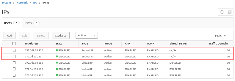
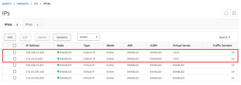
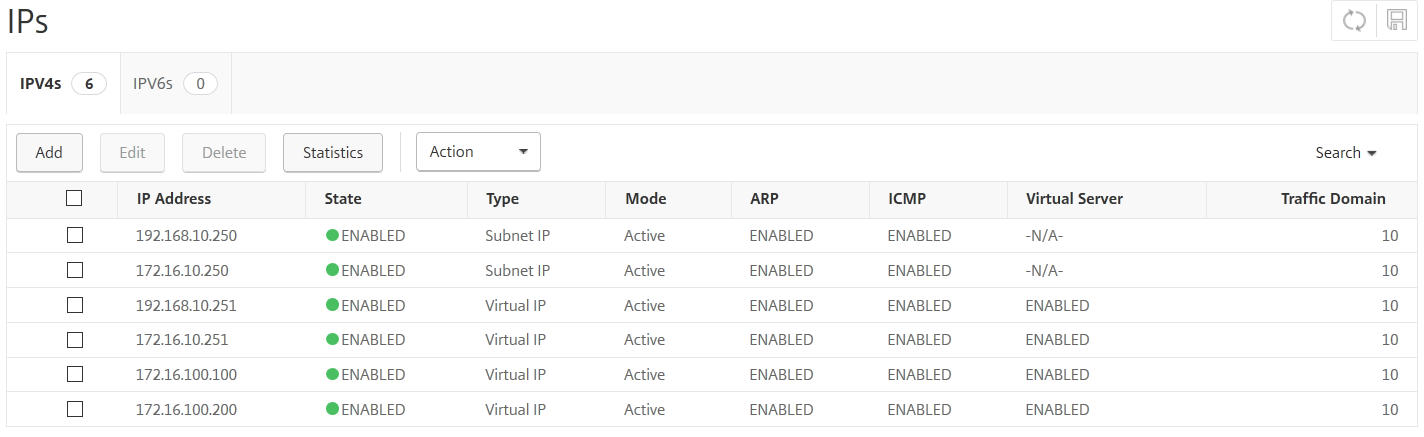
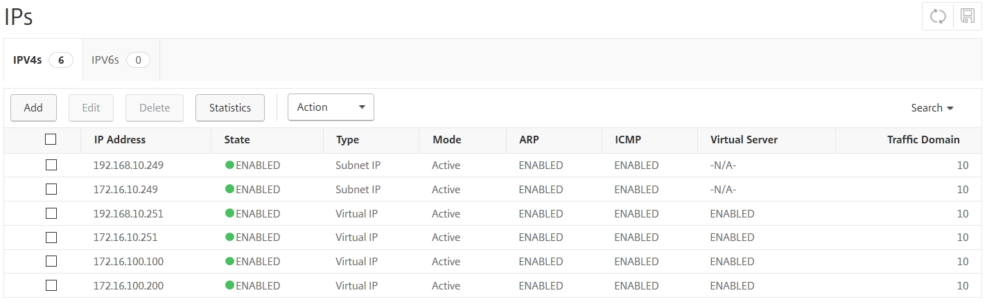
設定確認(Virtual IP)
メニューの[System]―[Network]―[IPs]―[IPV4s]を選択し、VIP設定を確認します。
LB01
LB02
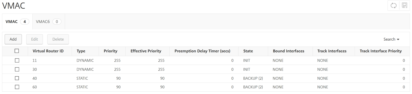
設定確認(VRRP)
メニューの[System]―[Network]―[VMAC]を選択し、VRRP設定を確認します。
LB01

LB02
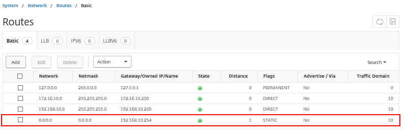
ルーティング設定
設定項目 |
設定値(LB01) |
設定値(LB02) |
|---|---|---|
宛先 |
0.0.0.0 |
0.0.0.0 |
サブネットマスク |
0.0.0.0 |
0.0.0.0 |
ゲートウェイアドレス |
192.168.10.254 |
192.168.10.254 |
Traffic Domain |
10 |
10 |
注釈
デフォルトゲートウェイ設定はSDPFポータルで実施してください。
設定確認
メニューの[System]―[Network]―[Routes]を選択し、ルーティング設定を確認します。
LB01 LB02 共通設定項目
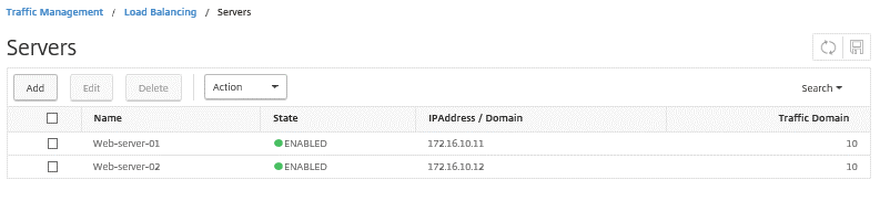
Webサーバーの登録設定
設定項目 |
設定値(LB01,LB02共通) |
設定値(LB01,LB02共通) |
|---|---|---|
Name |
Web-server-01 |
Web-server-02 |
IPAddress |
172.16.10.11/24 |
172.16.10.12/24 |
Traffic Domain |
10 |
10 |
注釈
設定方法の詳細は、サーバーを登録・編集・削除する機能 をご覧ください。
設定確認
LB01 LB02 共通設定項目
サービスグループ設定
設定項目 |
設定値(LB01) |
設定値(LB02) |
|---|---|---|
Service Name |
HTTP |
HTTP |
Existing Server |
WebServer01(172.16.10.11) |
WebServer01(172.16.10.11) |
WebServer02(172.16.10.12) |
WebServer02(172.16.10.12) |
|
Protocol |
HTTP |
HTTP |
Port |
80 |
80 |
Monitors |
http |
http |
Traffic Domain |
10 |
10 |
注釈
設定方法の詳細は、サービスグループを登録・編集・削除する機能 をご覧ください。
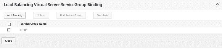
設定確認
メニュー[Traffic Management]-[Load Balancing]-[Service Group]へと進み、右メニューに表示された登録済みのサービスグループをダブルクリックし、設定を確認します。
LB01 LB02 共通設定項目
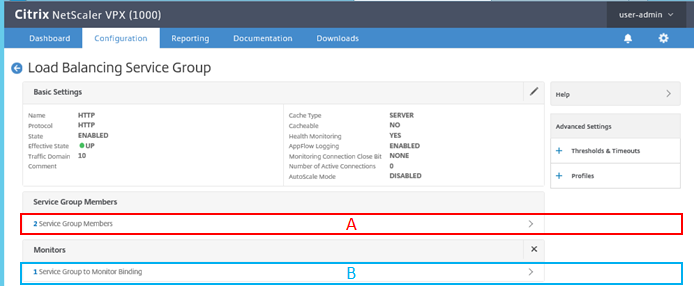
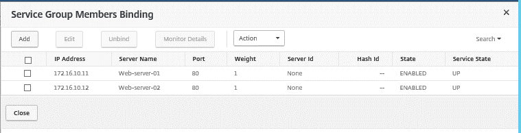
Service Group Members
上記画像中のA部分をクリックし、振り分け先となる仮想Webサーバー設定を確認します。
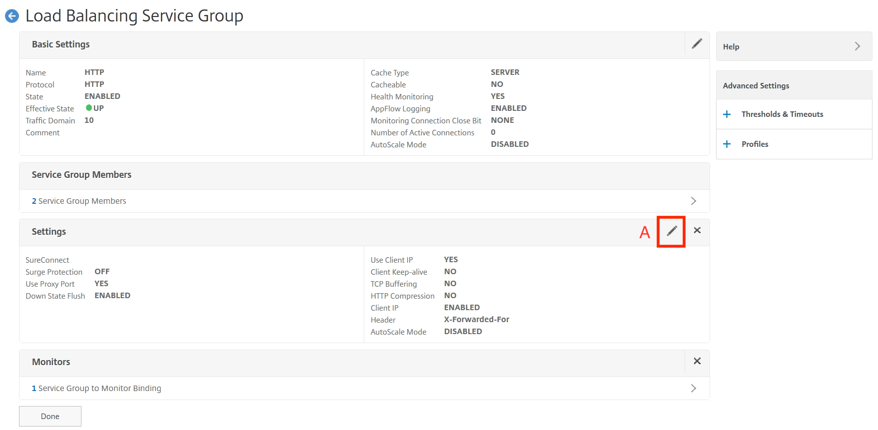
Enable Use Client IP
下記画像中のA部分をクリックし、Use Client IPを有効化します。
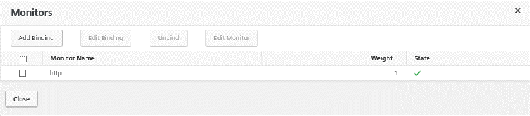
Monitors
上記画像中のB部分をクリックし、Monitorが設定されていることを確認します。
注釈
Use Client IPを有効化することで、Client端末のIPアドレスはバランシングされる際にLBのIPアドレスにSNAT変換されません。この設定はデフォルトで無効です。
WebサーバーにClient端末のIPアドレスが通知されます。
バーチャルサーバー設定
実際に外部から通信する宛先となるバーチャルサーバーを設定します。
HTTP通信用バーチャルサーバー設定
外部からHTTP通信を行うバーチャルサーバーの設定を行います。
使用するパラメータは以下のとおりです。
設定項目 |
設定値(LB01) |
設定値(LB02) |
|---|---|---|
Name |
http-vserver |
http-vserver |
Protocol |
HTTP |
HTTP |
IP Address Type |
IP Address |
IP Address |
IP Address |
172.16.100.100 |
172.16.100.100 |
Port |
80 |
80 |
Traffic Domain |
10 |
10 |
設定確認
メニューの[Traffic Management]―[Load Balancing]―[Virtual Servers]を選択し、右メニューに表示された登録済みのサービスグループ名[http-vserver]をダブルクリックし、設定を確認します。
LB01 LB02 共通設定項目
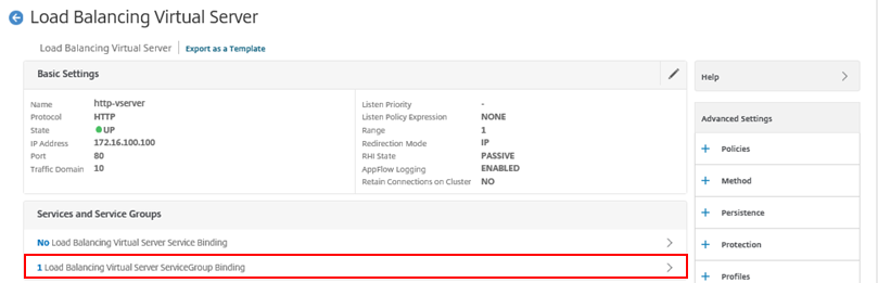
Load Balancing Virtual Server Service Group Binding
上記画像中の赤枠部分をクリックし、サービスグループが指定されていることを確認します。

SSLオフロード通信用バーチャルサーバー設定
設定項目 |
設定値(LB01) |
設定値(LB02) |
|---|---|---|
Name |
ssl-vserver |
ssl-vserver |
Protocol |
SSL |
SSL |
IP Address Type |
IP Address |
IP Address |
IP Address |
172.16.100.200 |
172.16.100.200 |
Port |
443 |
443 |
Server Certificate |
WEBSERVER-Keypair |
WEBSERVER-Keypair |
CA Certificate |
INTERCA-keyPair |
INTERCA-keyPair |
Traffic Domain |
10 |
10 |
注釈
必ず認証局が発行したSSLサーバー証明書をご使用ください。
設定方法は、証明書を登録する方法 、SSLオフロードの設定 をご覧ください。
設定確認
メニュー[Traffic Management]-[Load Balancing]-[Virtual Servers]へと進み、右メニューに表示された登録済みのサービスグループ名[ssl-vserver]をダブルクリックし、設定を確認します。
LB01 LB02 共通設定項目
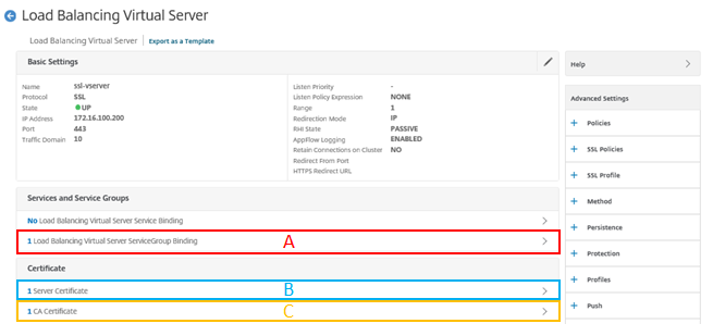
Load Balancing Virtual Server Service Group Binding
上記画像中のA部分をクリックし、サービスグループが指定されていることを確認します。
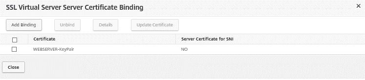
SSL Virtual Server Service Certificate Binding
上記画像中のB部分をクリックし、SSLサーバー証明書が設定されていることを確認します。
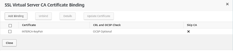
SSL Virtual Server CA Certificate Binding
上記画像中のC部分をクリックし、CA証明書が設定されていることを確認します。
これでLBの設定が完了しました。
2.5. 通信の流れ
正常通信時の状態確認
正常通信時のFWの状態は以下のように確認できます。
VRRPの状態
FW-01がMasterであることを確認します。
user01@FW-01> show vrrp
Interface     State       Group   VR state VR Mode   Timer    Type   Address
ge-0/0/0.0    up             30   master   Active      A  0.371 lcl    192.168.10.253
                                                                vip    192.168.10.254
ge-0/0/1.0    up             20   master   Active      A  0.359 lcl    192.168.0.253
                                                                vip    192.168.0.254
ge-0/0/2.0    up             10   master   Active      A  0.899 lcl    10.0.10.253
                                                                vip    10.0.10.254
FW-02がBackupであることを確認します。
user01@FW-02> show vrrp
Interface     State       Group   VR state VR Mode   Timer    Type   Address
ge-0/0/0.0    up             30   backup   Active      D  3.349 lcl    192.168.10.252
                                                                vip    192.168.10.254
                                                                mas    192.168.10.253
ge-0/0/1.0    up             20   backup   Active      D  3.531 lcl    192.168.0.252
                                                                vip    192.168.0.254
                                                                mas    192.168.0.253
ge-0/0/2.0    up             10   backup   Active      D  3.027 lcl    10.0.10.252
                                                                vip    10.0.10.254
                                                                mas    10.0.10.253
正常通信時のLBの状態は以下のように確認できます。
VRRPの状態
メニュー[System]-[Network]-[VMAC]へと進み、VRRP設定を確認します。
LB-01がMasterであることを確認します。
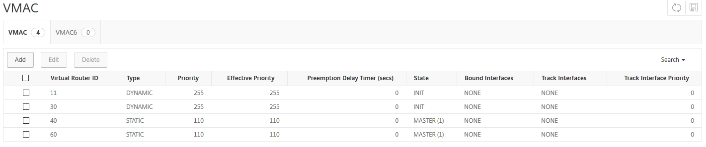
LB-02がBackupであることを確認します。

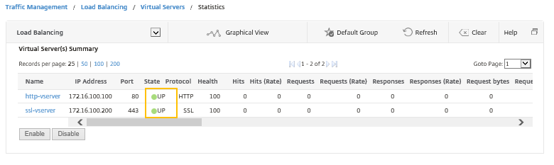
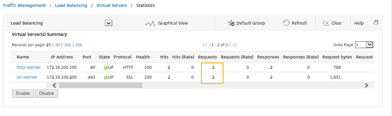
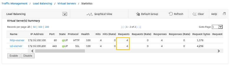
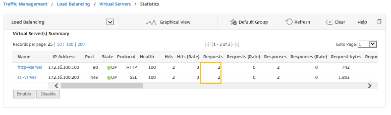
バーチャルサーバーの状態
メニューの[Traffic Management]―[Load Balancing]―[Virtual Servers]―[statistics]を選択し、バーチャルサーバーの状態がそれぞれUPであることを確認します。
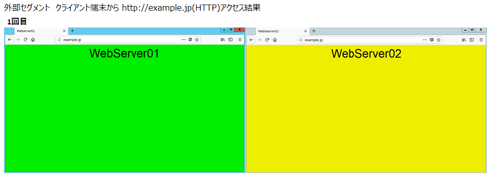
Client端末の接続確認
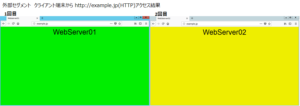
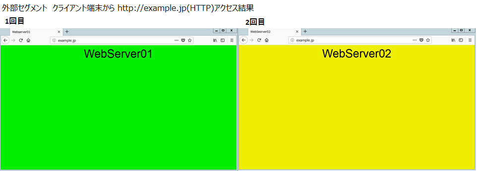
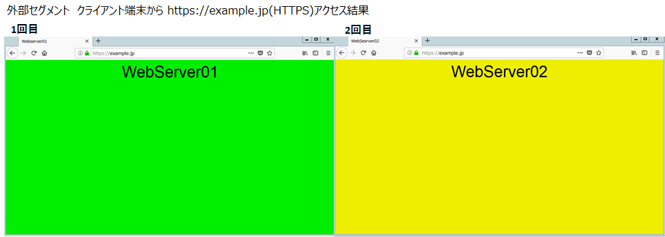
外部Client端末から HTTP通信・HTTPS通信を行います。
HTTP通信・HTTPS通信(それぞれ2回通信)[OK]
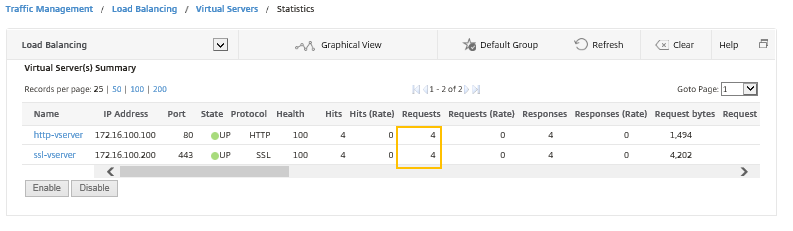
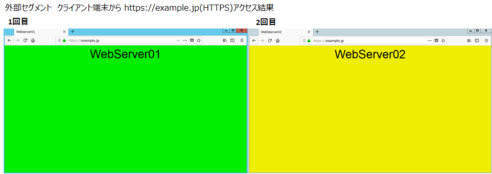
通信がバーチャルサーバー「http-vserver」「ssl-vserver」へヒットし「WebServer01,02」に振り分けられていることを確認します。

外部セグメントClient端末のブラウザー画面(HTTP通信)
外部セグメントClient端末のブラウザー画面(HTTPS通信)

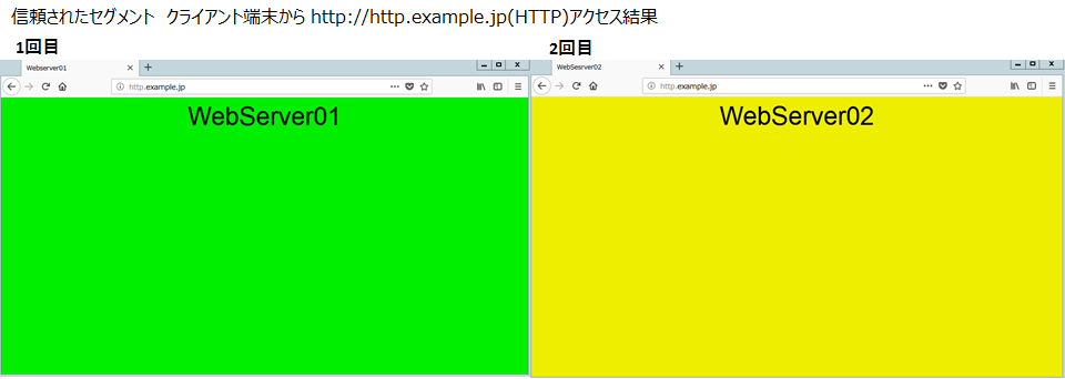
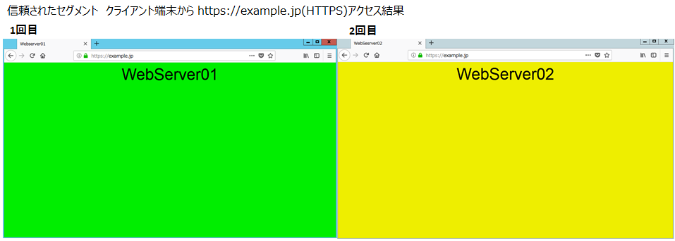
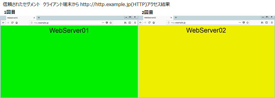
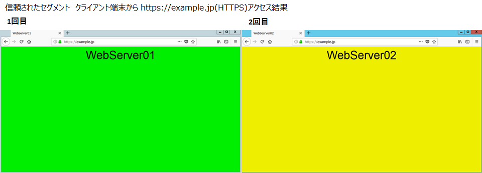
信頼されたClient端末からHTTP通信・HTTPS通信を行います。
HTTP通信・HTTPS通信(それぞれ2回通信)[OK]
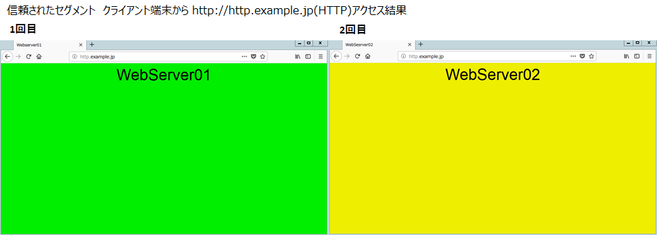
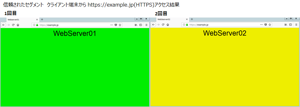
通信がバーチャルサーバー「http-vserver」「ssl-vserver」へヒットし「WebServer01,02」に振り分けられていることを確認します。
信頼されたClient端末のブラウザー画面(HTTP通信)
信頼されたClient端末のブラウザー画面(HTTPS通信)
以上で正常時の確認を終了します。
2.6. ファイアウォール障害発生時の通信の流れ
障害発生時はFW-02に経路が切り替わります。
障害発生時の状態確認
障害発生時のFWの状態は以下のように確認できます。
VRRPの状態
FW-01のVRRPが起動していないことを確認します。
user01@FW-01> show vrrp
VRRP is not running
注釈
FW-01のVRRPは停止中のため、状態は表示されません。
FW-02がMasterであることを確認します。
user01@FW-02> show vrrp
Interface     State       Group   VR state VR Mode   Timer    Type   Address
ge-0/0/0.0    up             30   master   Active      A  0.066 lcl    192.168.10.252
                                                                vip    192.168.10.254
ge-0/0/1.0    up             20   master   Active      A  0.744 lcl    192.168.0.252
                                                                vip    192.168.0.254
ge-0/0/2.0    up             10   master   Active      A  0.778 lcl    10.0.10.252
                                                                vip    10.0.10.254
注釈
LBの状態確認は正常時と変わりありませんので省略します。
Client端末の接続確認
FW障害発生時でも経路が切り替わり、問題なく通信が可能なことを確認するため外部セグメントClient端末からHTTP通信・HTTPS通信を行います。
HTTP・HTTPS通信(それぞれ2回通信)[OK]
通信がバーチャルサーバー「http-vserver」「ssl-vserver」へヒットし「WebServer01,02」 に振り分けられていることを確認します。
外部セグメントClient端末のブラウザー画面(HTTP通信)
外部セグメントClient端末のブラウザー画面(HTTPS通信)
続いて、信頼されたClient端末からHTTP通信・HTTPS通信を行います。
HTTP・HTTPS通信(それぞれ2回通信)[OK]
通信がバーチャルサーバー「http-vserver」「ssl-vserver」へヒットし「WebServer01,02」 に振り分けられていることを確認できます。
信頼されたClient端末のブラウザー画面(HTTP通信)
信頼されたClient端末のブラウザー画面(HTTP通信)
以上で、FW障害発生時の確認を終了します。
2.7. ロードバランサー障害発生時の通信の流れ
障害発生時はLB-02に経路が切り替わります。
注釈
LBはFWとは異なり製品仕様として手動でVRRPを無効化できません。そのため、今回はPriority値変更にてインスタンス障害を再現しています。
その他、強制的にVRRPを切り替えるには以下の方法があります。
すべてのVIPをdisableにし、VMAC設定を削除する。
インスタンスを再起動する。(Preemptionを有効にしている場合はPriorityに従い切り戻りが発生します)
※VMAC削除でVRRPを停止し、すべてのIPリソースを停止させておくと確実に切り替わり先で応答できます。
障害発生時の状態確認
障害発生時のLBの状態は以下のように確認できます。
※VRRPの切り替えのためLB01のPriority値を110から50へ変更しています。LB-02のPriority値は90です。
VRRPの状態
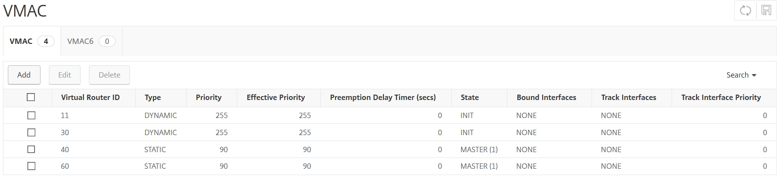
メニューの[System]―[Network]―[VMAC]を選択し、VRRP設定を確認します。
LB-01がBackupであることを確認します。
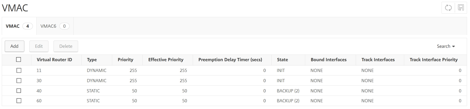
LB-02がMasterであることを確認します。
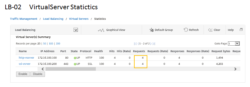
バーチャルサーバーの状態
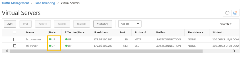
メニューの[Traffic Management]―[Load Balancing]―[Virtual Servers]―[statistics]を選択し、バーチャルサーバーの状態がそれぞれUPであることを確認します。
Client端末の接続確認
LB障害発生時でも問題なく通信できることを確認するため外部セグメントのClient端末からHTTP通信・HTTPS通信を行います。
HTTP通信・HTTPS通信(それぞれ2回通信)[OK]
通信がバーチャルサーバー「http-vserver」「ssl-vserver」へヒットし「WebServer01,02」 に振り分けられていることを確認できます。
外部セグメントClient端末のブラウザー画面(HTTP通信)
外部セグメントClient端末のブラウザー画面(HTTPS通信)
続いて、信頼されたClient端末からHTTP通信・HTTPS通信を行います。
HTTP通信・HTTPS通信(それぞれ2回通信)[OK]
通信がバーチャルサーバー「http-vserver」「ssl-vserver」へヒットし「WebServer01,02」に振り分けられていることを確認できます。
信頼されたClient端末のブラウザー画面(HTTP通信)
信頼されたClient端末のブラウザー画面(HTTPS通信)
以上でLB障害発生時の確認を終了します。