1.5. グローバルIPアドレス1個を利用したインターネットゲートウェイ接続(NAT+上下VRRP冗長構成)
1.5.1. システム構成図
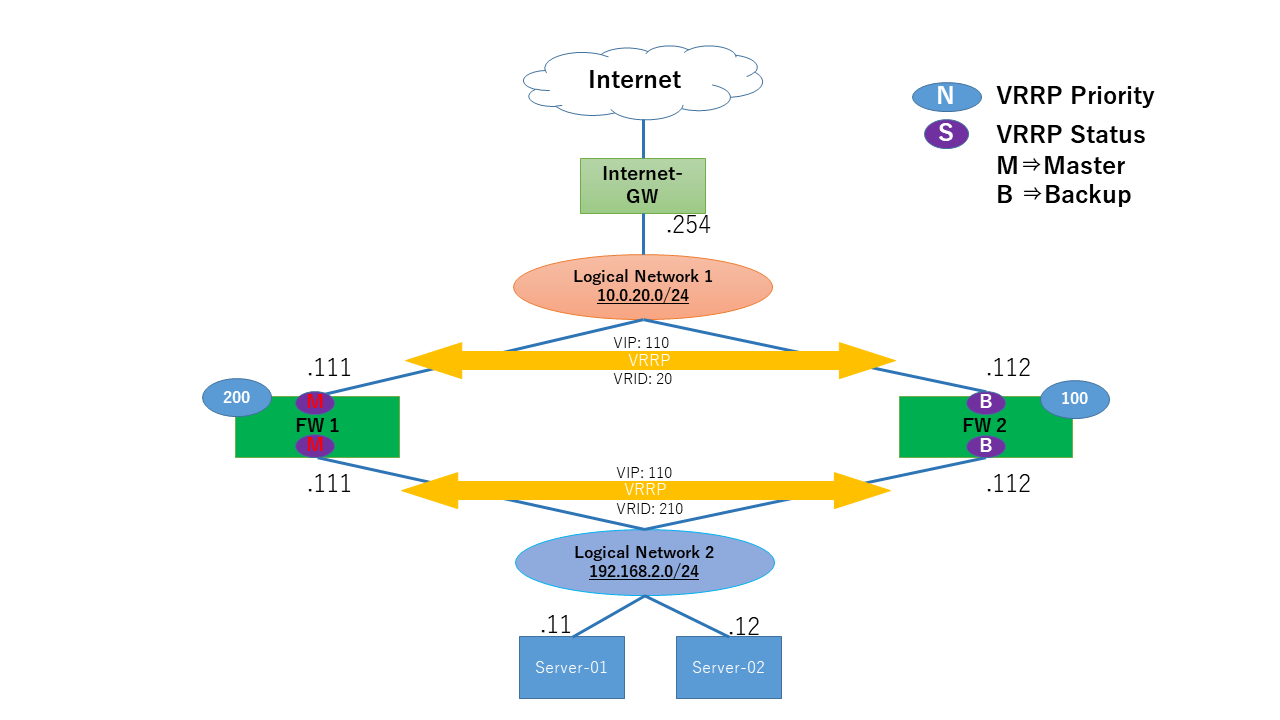
Server-01、02がFWを経由し、インターネットゲートウェイへアクセスできるよう構成しています。 Server-01、02のゲートウェイとして、FW01、02でVRRPを設定した冗長構成としています。 Server-01、02からインターネットゲートウェイへの通信をFWでSNATする構成としています。
1.5.2. FW設定の内容
FWインターフェイス設定
下記のコマンドを実行して、インターフェイスの設定を実施します。
FW01
set security zones security-zone untrust interfaces ge-0/0/1.0
set security zones security-zone trust interfaces ge-0/0/3.0
set interfaces ge-0/0/1 unit 0 family inet address 10.0.20.111/24
set interfaces ge-0/0/3 unit 0 family inet address 192.168.2.111/24
FW02
set security zones security-zone untrust interfaces ge-0/0/1.0
set security zones security-zone trust interfaces ge-0/0/3.0
set interfaces ge-0/0/1 unit 0 family inet address 10.0.20.112/24
set interfaces ge-0/0/3 unit 0 family inet address 192.168.2.112/24
VRRP設定
VRRP通信許可設定後、FWに以下を設定します。
FW01
set security zones security-zone untrust interfaces ge-0/0/1.0 host-inbound-traffic protocols vrrp
set security zones security-zone trust interfaces ge-0/0/3.0 host-inbound-traffic protocols vrrp
set interfaces ge-0/0/1 unit 0 family inet address 10.0.20.111/24 vrrp-group 20 virtual-address 10.0.20.110
set interfaces ge-0/0/1 unit 0 family inet address 10.0.20.111/24 vrrp-group 20 priority 200
set interfaces ge-0/0/1 unit 0 family inet address 10.0.20.111/24 vrrp-group 20 preempt
set interfaces ge-0/0/1 unit 0 family inet address 10.0.20.111/24 vrrp-group 20 accept-data
set interfaces ge-0/0/1 unit 0 family inet address 10.0.20.111/24 vrrp-group 20 advertise-interval 5
set interfaces ge-0/0/3 unit 0 family inet address 192.168.2.111/24 vrrp-group 210 virtual-address 192.168.2.110
set interfaces ge-0/0/3 unit 0 family inet address 192.168.2.111/24 vrrp-group 210 priority 200
set interfaces ge-0/0/3 unit 0 family inet address 192.168.2.111/24 vrrp-group 210 preempt
set interfaces ge-0/0/3 unit 0 family inet address 192.168.2.111/24 vrrp-group 210 accept-data
set interfaces ge-0/0/3 unit 0 family inet address 192.168.2.111/24 vrrp-group 210 advertise-interval 5
FW02
set security zones security-zone untrust interfaces ge-0/0/1.0 host-inbound-traffic protocols vrrp
set security zones security-zone trust interfaces ge-0/0/3.0 host-inbound-traffic protocols vrrp
set interfaces ge-0/0/1 unit 0 family inet address 10.0.20.112/24 vrrp-group 20 virtual-address 10.0.20.110
set interfaces ge-0/0/1 unit 0 family inet address 10.0.20.112/24 vrrp-group 20 priority 100
set interfaces ge-0/0/1 unit 0 family inet address 10.0.20.112/24 vrrp-group 20 preempt
set interfaces ge-0/0/1 unit 0 family inet address 10.0.20.112/24 vrrp-group 20 accept-data
set interfaces ge-0/0/1 unit 0 family inet address 10.0.20.112/24 vrrp-group 20 advertise-interval 5
set interfaces ge-0/0/3 unit 0 family inet address 192.168.2.112/24 vrrp-group 210 virtual-address 192.168.2.110
set interfaces ge-0/0/3 unit 0 family inet address 192.168.2.112/24 vrrp-group 210 priority 100
set interfaces ge-0/0/3 unit 0 family inet address 192.168.2.112/24 vrrp-group 210 preempt
set interfaces ge-0/0/3 unit 0 family inet address 192.168.2.112/24 vrrp-group 210 accept-data
set interfaces ge-0/0/3 unit 0 family inet address 192.168.2.112/24 vrrp-group 210 advertise-interval 5
注釈
ファイアウォール(vSRX)のVRRPの切り替わり時間として、Advertise Interval×3回に加え4秒程度必要であるため、Advertise Intervalを5秒に設定した場合、障害発生からトラフィックの切り替わり完了までに19秒程度必要となる想定です。 本設定を変更する場合、先にBackup側のFWから実施してください。Master側を先に変更すると、Backup側へのHelloパケットの送信間隔が変わり、Backup側もMasterに昇格して両装置がMasterになる恐れがあります。
NAT設定(SNAT)
サーバーの送信元IPアドレスを、FWにてSNATを行う設定を以下に示します。
FW01
set security nat source pool POOL1 address 203.0.113.1/32
set security nat source rule-set RULE from zone trust
set security nat source rule-set RULE to zone untrust
set security nat source rule-set RULE rule 10 match source-address 192.168.2.0/24
set security nat source rule-set RULE rule 10 then source-nat pool POOL1
FW02
set security nat source pool POOL1 address 203.0.113.1/32
set security nat source rule-set RULE from zone trust
set security nat source rule-set RULE to zone untrust
set security nat source rule-set RULE rule 10 match source-address 192.168.2.0/24
set security nat source rule-set RULE rule 10 then source-nat pool POOL1
設定内容の確認
前述の設定が正しく投入されている場合、以下の出力(一部抜粋)を確認できます。
FW01
user@FW01> show configuration |no-more

     nat {
        source {
            pool POOL1 {
                address {
                    203.0.113.1/32;
                }
            }
            rule-set RULE {
                from zone trust;
                to zone untrust;
                rule 10 {
                    match {
                        source-address 192.168.2.0/24;
                    }
                    then {
                        source-nat {
                            pool {
                                POOL1;
                            }
                        }
                    }
                }
            }
FW02
user@FW02> show configuration |no-more

     nat {
        source {
            pool POOL1 {
                address {
                    203.0.113.1/32;
                }
            }
            rule-set RULE {
                from zone trust;
                to zone untrust;
                rule 10 {
                    match {
                        source-address 192.168.2.0/24;
                    }
                    then {
                        source-nat {
                            pool {
                                POOL1;
                            }
                        }
                    }
                }
            }
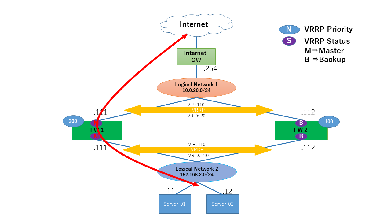
1.5.3. 通信の流れ
Server-01、02は正常時、MasterであるFW01を通してインターネットゲートウェイへ通信します。
正常通信時の状態確認
正常通信時のFWの状態は以下のように確認できます。
VRRPの状態
FW01がMasterであることを確認できます。
user@FW01> show vrrp
Interface     State       Group   VR state VR Mode   Timer    Type   Address
ge-0/0/1.0    up             20   master   Active      A  7.834 lcl    10.0.20.111
                                                                vip    10.0.20.110
ge-0/0/3.0    up            210   master   Active      A  13.791lcl    192.168.2.111
                                                                vip    192.168.2.110
FW02がBackupであることを確認できます。
user@FW02> show vrrp
Interface     State       Group   VR state VR Mode   Timer    Type   Address
ge-0/0/1.0    up             20   backup   Active      D  46.938lcl    10.0.20.112
                                                                vip    10.0.20.110
                                                                mas    10.0.20.111
ge-0/0/3.0    up            210   backup   Active      D  50.527lcl    192.168.2.112
                                                                vip    192.168.2.110
                                                                mas    192.168.2.111
NAT変換の状態
FW01を通過するServer-01、02の送信元IPアドレスが、SNATの設定どおり変換されていることを確認できます。
user@FW01> show security flow session

Session ID: 233, Policy name: default-permit/5, Timeout: 2, Valid
  In: 192.168.2.11/3 --> x.x.x.x/29412;icmp, Conn Tag: 0x0, If: ge-0/0/3.0, Pkts: 1, Bytes: 84,
  Out: x.x.x.x/29412 --> 203.0.113.1/29142;icmp, Conn Tag: 0x0, If: ge-0/0/1.0, Pkts: 1, Bytes: 84,

Session ID: 234, Policy name: default-permit/5, Timeout: 2, Valid
  In: 192.168.2.11/4 --> x.x.x.x/29412;icmp, Conn Tag: 0x0, If: ge-0/0/3.0, Pkts: 1, Bytes: 84,
  Out: x.x.x.x/29412 --> 203.0.113.1/31109;icmp, Conn Tag: 0x0, If: ge-0/0/1.0, Pkts: 1, Bytes: 84,

Session ID: 235, Policy name: default-permit/5, Timeout: 4, Valid
  In: 192.168.2.11/5 --> x.x.x.x/29412;icmp, Conn Tag: 0x0, If: ge-0/0/3.0, Pkts: 1, Bytes: 84,
  Out: x.x.x.x/29412 --> 203.0.113.1/15789;icmp, Conn Tag: 0x0, If: ge-0/0/1.0, Pkts: 1, Bytes: 84,
Total sessions: 4


user@FW01> show security flow session

Session ID: 217, Policy name: default-permit/5, Timeout: 2, Valid
  In: 192.168.2.12/48272 --> x.x.x.x/44447;udp, Conn Tag: 0x0, If: ge-0/0/3.0, Pkts: 2, Bytes: 2954,
  Out: x.x.x.x/44447 --> 203.0.113.1/24777;udp, Conn Tag: 0x0, If: ge-0/0/1.0, Pkts: 0, Bytes: 0,

Session ID: 219, Policy name: default-permit/5, Timeout: 2, Valid
  In: 192.168.2.12/48272 --> x.x.x.x/44448;udp, Conn Tag: 0x0, If: ge-0/0/3.0, Pkts: 2, Bytes: 2954,
  Out: x.x.x.x/44448 --> 203.0.113.1/11069;udp, Conn Tag: 0x0, If: ge-0/0/1.0, Pkts: 0, Bytes: 0,

Session ID: 221, Policy name: default-permit/5, Timeout: 4, Valid
  In: 192.168.2.12/48272 --> x.x.x.x/44449;udp, Conn Tag: 0x0, If: ge-0/0/3.0, Pkts: 2, Bytes: 2954,
  Out: x.x.x.x/44449 --> 203.0.113.1/3876;udp, Conn Tag: 0x0, If: ge-0/0/1.0, Pkts: 0, Bytes: 0,
正常通信時の状態確認
以下のとおり、インターネットゲートウェイ上のサーバー(x.x.x.x)と疎通できていることを確認できます。 また、tracerouteの結果からFW01を経由して通信が行われていることを確認できます。
Server-01
[server-01 ~]# ping -c 5 x.x.x.x
PING x.x.x.x (x.x.x.x) 56(84) bytes of data.
64 bytes from x.x.x.x: icmp_seq=1 ttl=50 time=8.07 ms
64 bytes from x.x.x.x: icmp_seq=2 ttl=50 time=4.76 ms
64 bytes from x.x.x.x: icmp_seq=3 ttl=50 time=4.33 ms
64 bytes from x.x.x.x: icmp_seq=4 ttl=50 time=3.64 ms
64 bytes from x.x.x.x: icmp_seq=5 ttl=50 time=3.95 ms

--- x.x.x.x ping statistics ---
5 packets transmitted, 5 received, 0% packet loss, time 4006ms
rtt min/avg/max/mdev = 3.645/4.954/8.077/1.608 ms
[server-01 ~]#

[server-01 ~]# traceroute x.x.x.x
traceroute to x.x.x.x (x.x.x.x) , 30 hops max, 60 byte packets
1 gateway (192.168.2.111) 5.674 ms 5.658 ms 5.686 ms
2 203.0.113.1 (203.0.113.1) 22.952 ms 22.899 ms 22.904 ms
3 203.0.113.2 (203.0.113.2) 11.339 ms 11.183 ms 11.167 ms
(中略)
13 xxxxx (x.x.x.x) 13.046 ms 14.567 ms 15.449 ms
[server-01 ~]#
Server-02
[server-02 ~]# ping -c 5 x.x.x.x
PING x.x.x.x (x.x.x.x) 56(84) bytes of data.
64 bytes from x.x.x.x: icmp_seq=1 ttl=50 time=8.07 ms
64 bytes from x.x.x.x: icmp_seq=2 ttl=50 time=4.76 ms
64 bytes from x.x.x.x: icmp_seq=3 ttl=50 time=4.33 ms
64 bytes from x.x.x.x: icmp_seq=4 ttl=50 time=3.64 ms
64 bytes from x.x.x.x: icmp_seq=5 ttl=50 time=3.95 ms

--- x.x.x.x ping statistics ---
5 packets transmitted, 5 received, 0% packet loss, time 4006ms
rtt min/avg/max/mdev = 3.645/4.954/8.077/1.608 ms
[server-02 ~]#

[server-02 ~]# traceroute x.x.x.x
traceroute to x.x.x.x (x.x.x.x), 30 hops max, 60 byte packets
1 gateway (192.168.2.111) 5.674 ms 5.658 ms 5.686 ms
2 203.0.113.1 (203.0.113.1) 22.952 ms 22.899 ms 22.904 ms
3 203.0.113.2 (203.0.113.2) 11.339 ms 11.183 ms 11.167 ms
(中略)
13 xxxxx (x.x.x.x) 13.046 ms 14.567 ms 15.449 ms
[server-02 ~]#
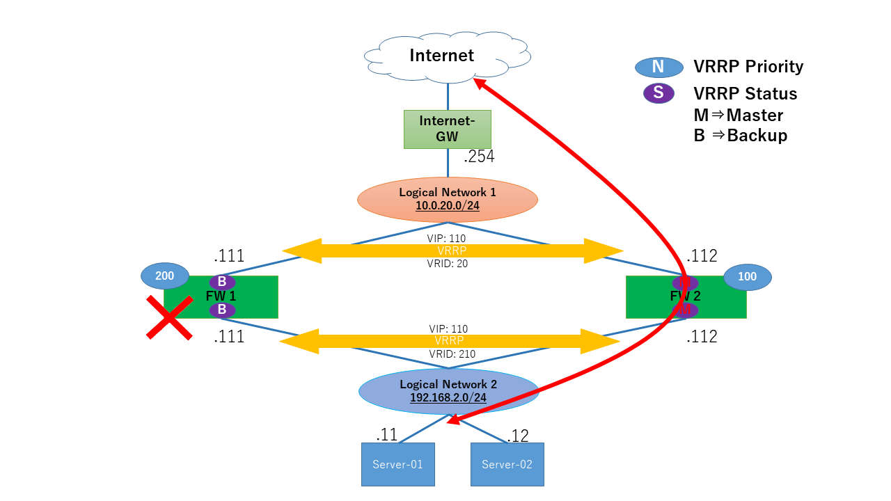
1.5.4. 障害発生時の通信の流れ
FW01にインスタンス障害が発生した場合、Server-01、02はFW02を通してインターネットゲートウェイへ通信します。
注釈
インスタンス障害の試験方法として、FW01 の インターフェイス を一時的に無効化する手法を採用しております。インターフェイスの無効化/有効化のコマンドは以下のとおりです。
無効化
# set interfaces [INTERFACE NAME] disable
有効化
# delete interfaces [INTERFACE NAME] disable

例
インターフェイス無効化の設定コマンド
# set interfaces ge-0/0/1.0 disable
# set interfaces ge-0/0/2.0 disable

インターフェイス有効化の設定コマンド
# delete interfaces ge-0/0/1.0 disable
# delete interfaces ge-0/0/2.0 disable
障害発生時の状態確認
障害発生時のFWの状態は以下のように確認できます。
FW01がMasterでないことを確認できます。
user@FW01> show vrrp
Interface     State       Group   VR state VR Mode   Timer    Type   Address
ge-0/0/1.0    down           20   init     Active      N  0.000 lcl    10.0.20.111
                                                                vip    10.0.20.110
ge-0/0/3.0    down          210   init     Active      N  0.000 lcl    192.168.2.111
                                                                vip    192.168.2.110
注釈
インターフェイスの無効化によりMasterが切り替わります。
FW02がMasterであることを確認できます。
user@FW02> show vrrp
Interface     State       Group   VR state VR Mode   Timer    Type   Address
ge-0/0/1.0    up             20   master   Active      A  17.851lcl    10.0.20.112
                                                                vip    10.0.20.110
ge-0/0/3.0    up            210   master   Active      A  7.713 lcl    192.168.2.112
                                                                vip    192.168.2.110
NAT変換の状態
FW-02を通過するServer-01、02の送信元IPアドレスが、SNATの設定どおり変換されていることを確認できます。
user@FW02> show security flow session

Session ID: 233, Policy name: default-permit/5, Timeout: 2, Valid
  In: 192.168.2.11/3 --> x.x.x.x/29412;icmp, Conn Tag: 0x0, If: ge-0/0/3.0, Pkts: 1, Bytes: 84,
  Out: x.x.x.x/29412 --> 203.0.113.1/29142;icmp, Conn Tag: 0x0, If: ge-0/0/1.0, Pkts: 1, Bytes: 84,

Session ID: 234, Policy name: default-permit/5, Timeout: 2, Valid
  In: 192.168.2.11/4 --> x.x.x.x/29412;icmp, Conn Tag: 0x0, If: ge-0/0/3.0, Pkts: 1, Bytes: 84,
  Out: x.x.x.x/29412 --> 203.0.113.1/31109;icmp, Conn Tag: 0x0, If: ge-0/0/1.0, Pkts: 1, Bytes: 84,

Session ID: 235, Policy name: default-permit/5, Timeout: 4, Valid
  In: 192.168.2.11/5 --> x.x.x.x/29412;icmp, Conn Tag: 0x0, If: ge-0/0/3.0, Pkts: 1, Bytes: 84,
  Out: x.x.x.x/29412 --> 203.0.113.1/15789;icmp, Conn Tag: 0x0, If: ge-0/0/1.0, Pkts: 1, Bytes: 84,
Total sessions: 4


user@FW02> show security flow session

Session ID: 239, Policy name: default-permit/5, Timeout: 2, Valid
  In: 192.168.2.12/3 --> x.x.x.x/4275;icmp, Conn Tag: 0x0, If: ge-0/0/3.0, Pkts: 1, Bytes: 84,
  Out: x.x.x.x/4275 --> 203.0.113.1/31308;icmp, Conn Tag: 0x0, If: ge-0/0/1.0, Pkts: 1, Bytes: 84,

Session ID: 240, Policy name: default-permit/5, Timeout: 2, Valid
  In: 192.168.2.12/4 --> x.x.x.x/4275;icmp, Conn Tag: 0x0, If: ge-0/0/3.0, Pkts: 1, Bytes: 84,
  Out: x.x.x.x/4275 --> 203.0.113.1/9436;icmp, Conn Tag: 0x0, If: ge-0/0/1.0, Pkts: 1, Bytes: 84,

Session ID: 241, Policy name: default-permit/5, Timeout: 4, Valid
  In: 192.168.2.12/5 --> x.x.x.x/4275;icmp, Conn Tag: 0x0, If: ge-0/0/3.0, Pkts: 1, Bytes: 84,
  Out: x.x.x.x/4275 --> 203.0.113.1/15015;icmp, Conn Tag: 0x0, If: ge-0/0/1.0, Pkts: 1, Bytes: 84,
Total sessions: 4
障害発生時の状態確認
以下のとおり、インターネットゲートウェイ上のサーバー(x.x.x.x)と疎通できていることを確認できます。 また、tracerouteの結果からFW02を経由して通信が行われていることを確認できます。
Server-01
[server-01 ~]# ping -c 5 x.x.x.x
PING x.x.x.x (x.x.x.x) 56(84) bytes of data.
64 bytes from x.x.x.x: icmp_seq=1 ttl=50 time=5.67 ms
64 bytes from x.x.x.x: icmp_seq=2 ttl=50 time=4.36 ms
64 bytes from x.x.x.x: icmp_seq=3 ttl=50 time=4.44 ms
64 bytes from x.x.x.x: icmp_seq=4 ttl=50 time=4.23 ms
64 bytes from x.x.x.x: icmp_seq=5 ttl=50 time=4.25 ms

--- x.x.x.x ping statistics ---
5 packets transmitted, 5 received, 0% packet loss, time 4006ms
rtt min/avg/max/mdev = 4.232/4.595/5.679/0.551 ms
[server-01 ~]#
[server-01 ~]# traceroute x.x.x.x
traceroute to x.x.x.x (x.x.x.x), 30 hops max, 60 byte packets
1 gateway (192.168.2.111) 5.674 ms 5.658 ms 5.686 ms
2 203.0.113.1 (203.0.113.1) 22.952 ms 22.899 ms 22.904 ms
3 203.0.113.2 (203.0.113.2) 11.339 ms 11.183 ms 11.167 ms
(中略)
13 xxxxx (x.x.x.x) 13.046 ms 14.567 ms 15.449 ms
[server-01 ~]#
server-02
[server-02 ~]# ping -c 5 x.x.x.x
PING x.x.x.x (x.x.x.x) 56(84) bytes of data.
64 bytes from x.x.x.x: icmp_seq=1 ttl=50 time=5.67 ms
64 bytes from x.x.x.x: icmp_seq=2 ttl=50 time=4.36 ms
64 bytes from x.x.x.x: icmp_seq=3 ttl=50 time=4.44 ms
64 bytes from x.x.x.x: icmp_seq=4 ttl=50 time=4.23 ms
64 bytes from x.x.x.x: icmp_seq=5 ttl=50 time=4.25 ms

--- x.x.x.x ping statistics ---
5 packets transmitted, 5 received, 0% packet loss, time 4006ms
[server-02 ~]# traceroute x.x.x.x
traceroute to x.x.x.x (x.x.x.x), 30 hops max, 60 byte packets
1 gateway (192.168.2.111) 5.674 ms 5.658 ms 5.686 ms
2 203.0.113.1 (203.0.113.1) 22.952 ms 22.899 ms 22.904 ms
3 203.0.113.2 (203.0.113.2) 11.339 ms 11.183 ms 11.167 ms
(中略)
13 xxxxx (x.x.x.x) 13.046 ms 14.567 ms 15.449 ms
[server-02 ~]#